Quick Start
1. Prepare Cables
Before getting started, prepare the required cables according to your application scenario:
| Interface Type | Purpose | Required Cable |
|---|---|---|
| WAN / LAN | Network connection (router / device communication) | RJ45 Ethernet cable |
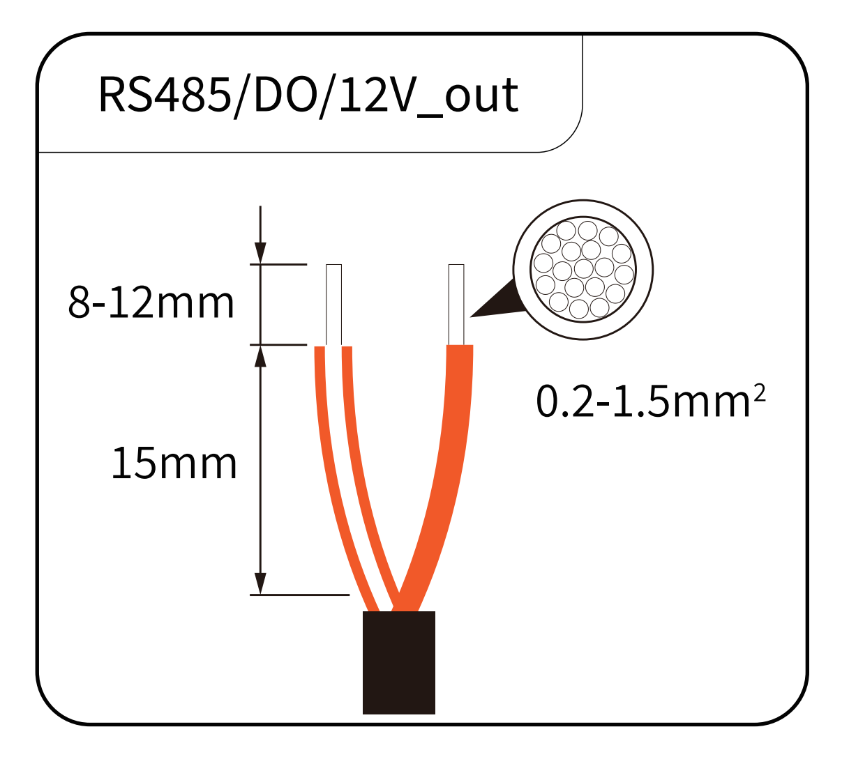
| RS485 / DO / 12V_OUT | Inverter / heat pump communication and control | RS485 signal cable |
| P1 | Smart meter data reading | RJ12 signal cable |
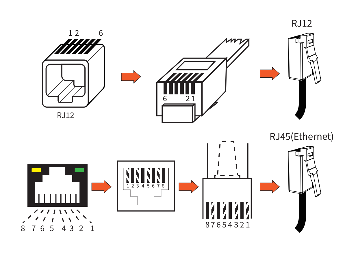
- Do not mix different cable types (RJ12 ≠ RJ45)
- Pay special attention to correct A/B wiring for RS485 communication
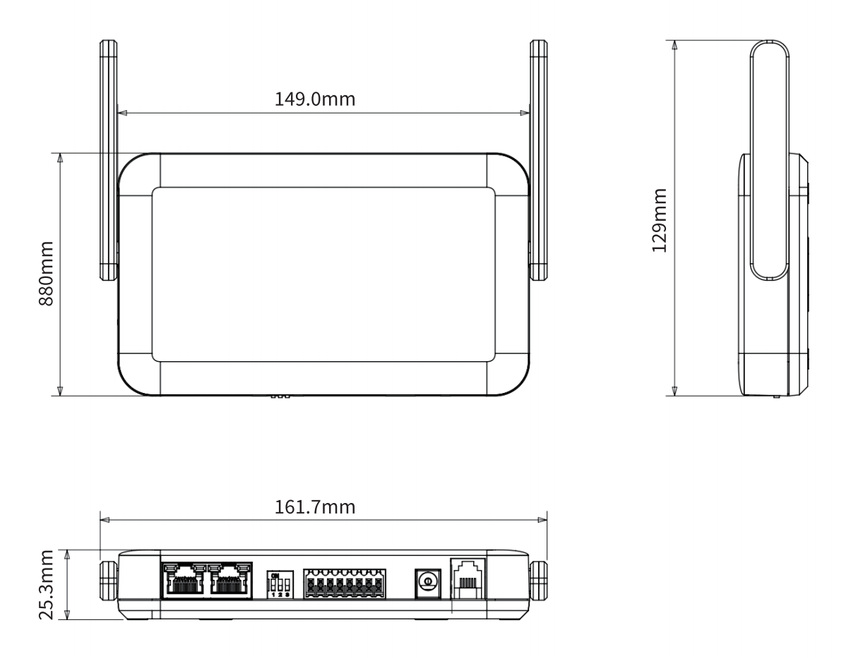
2. Device Installation
Choose an appropriate installation location to ensure stable operation:
- Well-ventilated area, avoid enclosed spaces
- Keep away from heat sources (e.g., radiators, direct sunlight)
- Avoid strong electromagnetic interference (e.g., distribution boxes, high-power electrical equipment)
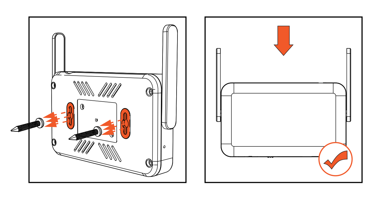
Installation Steps:
- Determine mounting positions: Mark screw positions on the installation surface according to the mounting slots on the back of the device.
- Fix the screws: Secure screws at the marked positions.
- Align the device: Align the rear mounting slots with the installed screws.
- Secure the device: Slide the device downward to lock it into place.
3. Electrical Connections
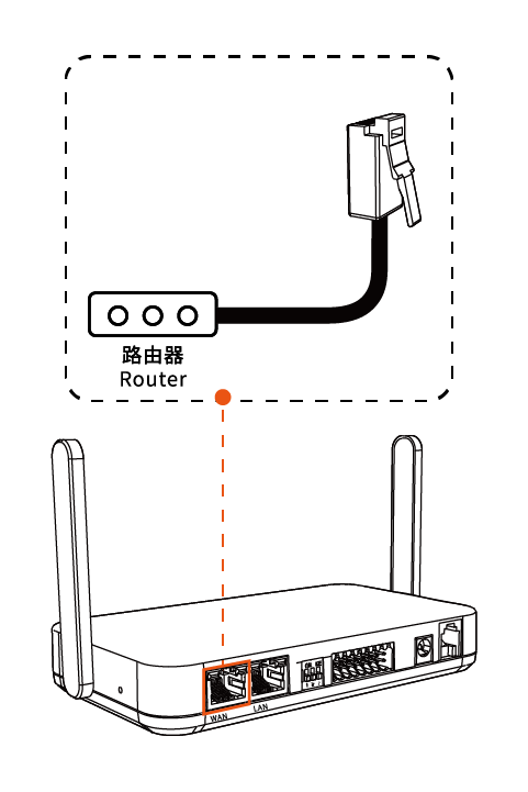
3.1 Connect the Ethernet Cable
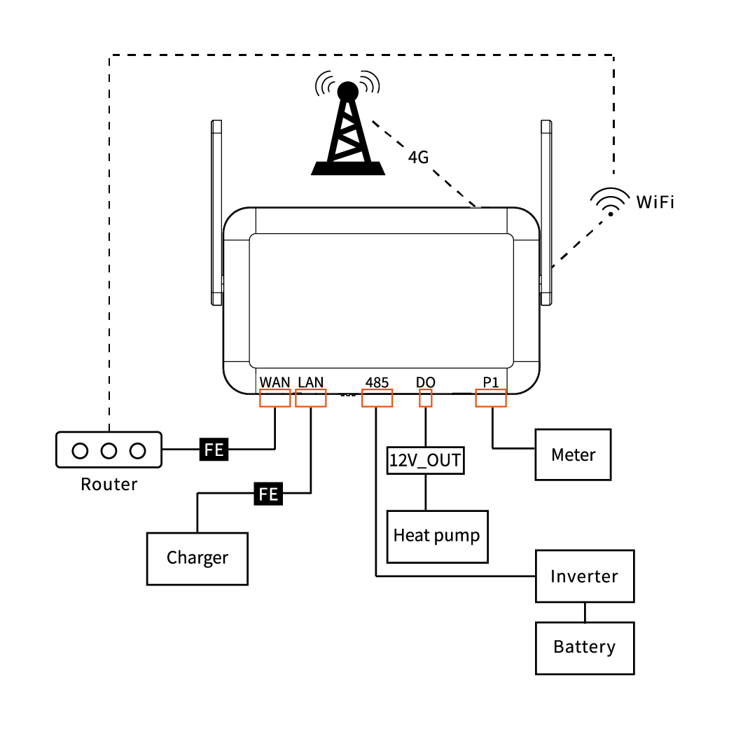
Connect the EMH-2 WAN port to the router LAN port using an RJ45 Ethernet cable.
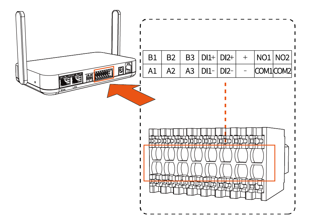
3.2 Signal Wiring
Insert Terminal Block
Insert the 8P×2 terminal connector into the corresponding device interface.
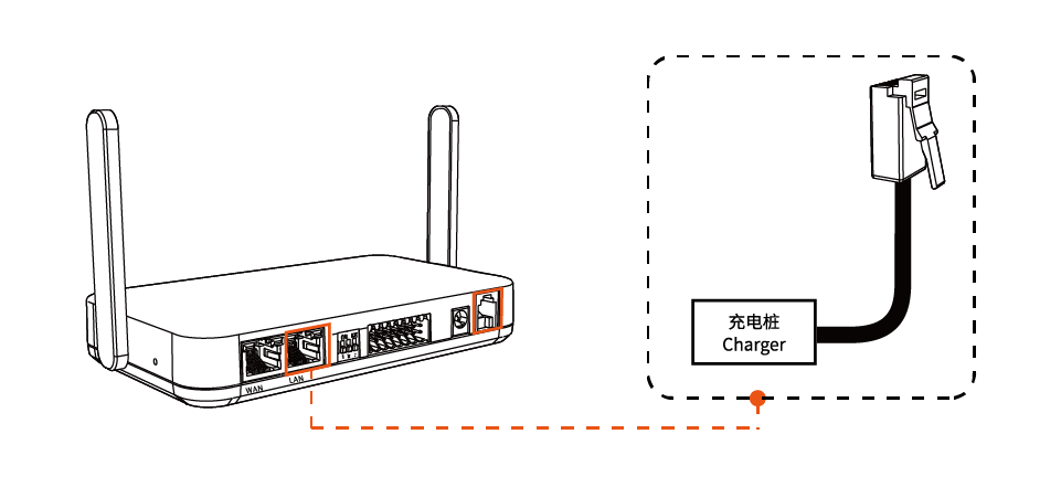
Connect EV Charger (if applicable)
Use an RJ45 cable to connect the EMH-2 LAN port to the EV charger.
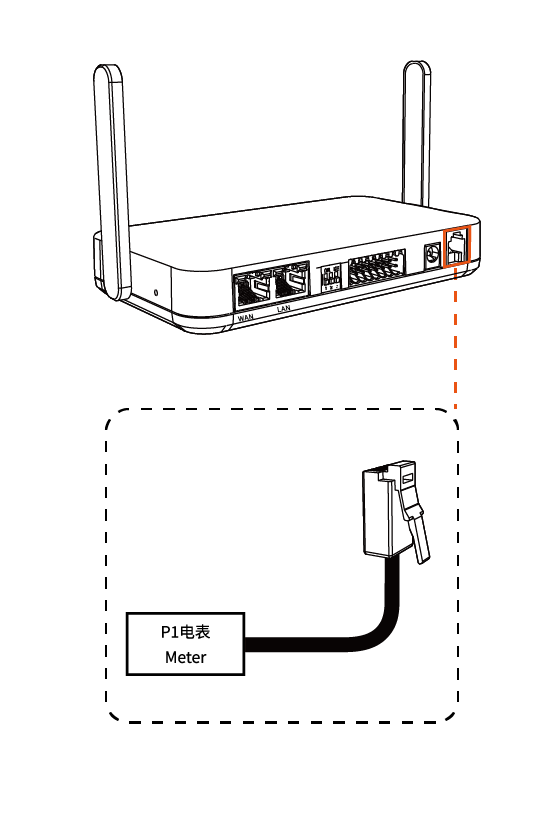
Connect P1 Smart Meter (if applicable)
Use an RJ12 cable to connect the EMH-2 P1 port to the meter P1 interface.
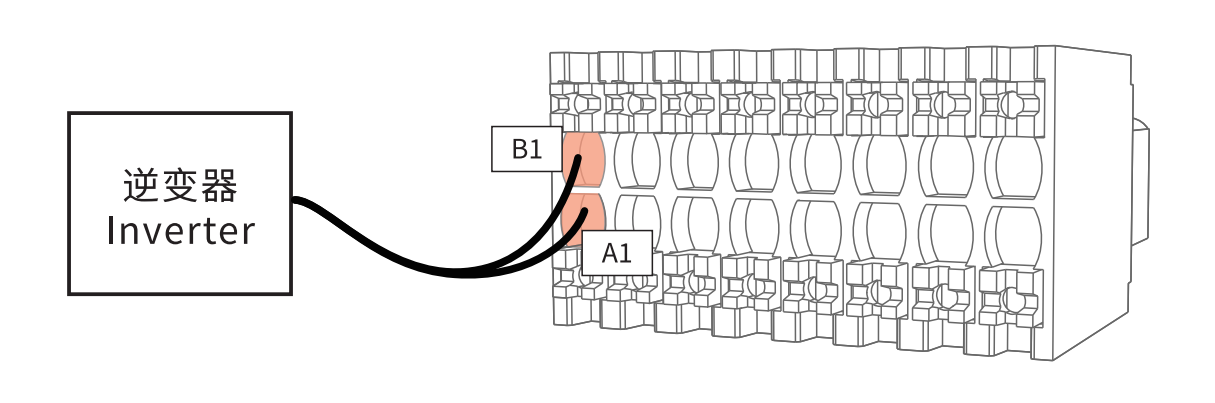
Connect Inverter
Connect RS485 communication wires to the 8P×2 terminal:
- RS485 A wire → terminal A port
- RS485 B wire → terminal B port
Ensure correct A/B wiring and connect to the same terminal group (e.g., A1/B1). Otherwise, communication will fail.
Connect Heat Pump
Select the appropriate connection method based on the SG Ready interface type of the heat pump:
- 1️⃣ Relay Control
- 2️⃣ Direct Connection
- EMH-2 + connects to EMH-2 NO1
- EMH-2 COM1 connects to external relay coil +
- EMH-2 - connects to external relay coil -
- Relay contact connects to heat pump
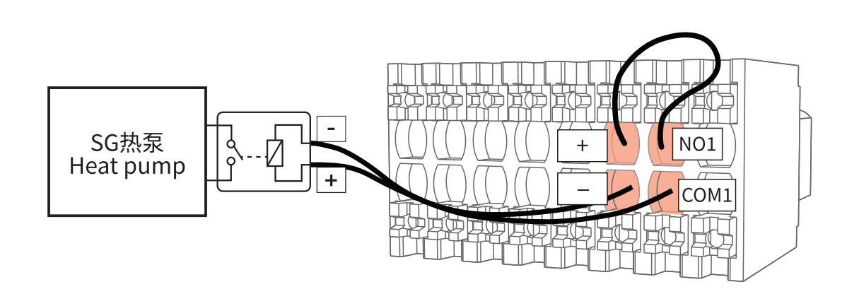
- Controls whether +12V is supplied to the relay coil via DO (NO1/COM1), indirectly controlling the heat pump
- Suitable for high-power or more stable control scenarios
EMH-2 DO output (NO1 / COM1) connects directly to the heat pump DI input
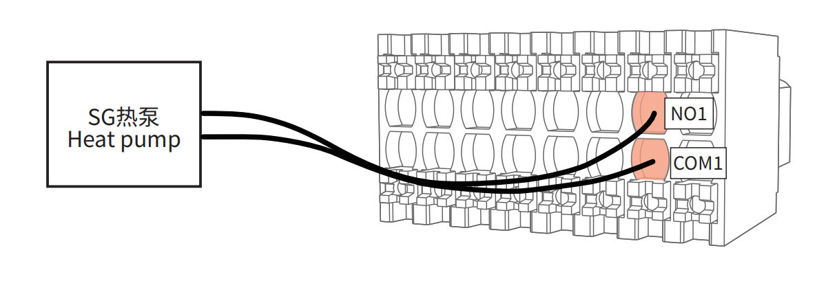
- Directly switches the signal via internal relay output
- Suitable for low-current control scenarios
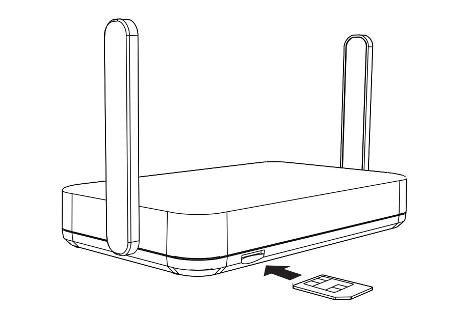
3.3 Insert 4G SIM Card
Insert the SIM card according to the diagram near the slot. The metal contacts should face upward, and the notched edge should face outward. Push the card in until it locks into place.
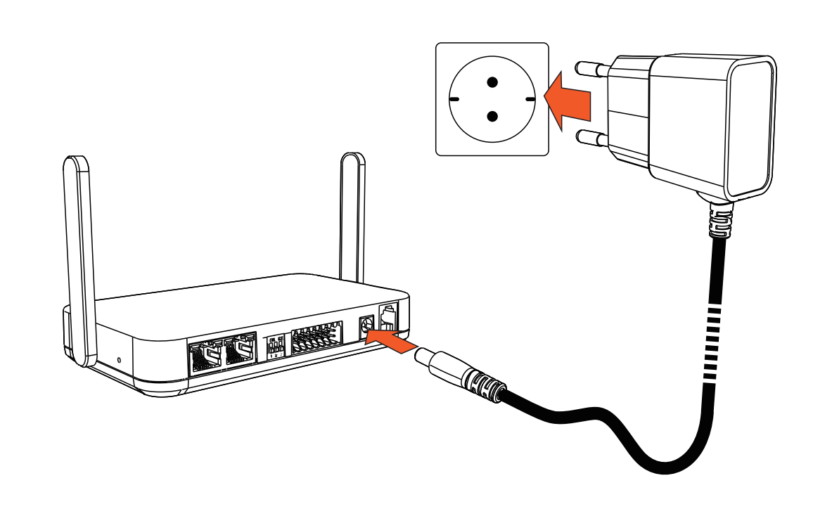
3.4 Power Connection
Use the original power adapter and plug the DC connector into the DC power port of the EMH-2 device.