System Access and Device Management
1. Overview
The firmware architecture platform is a local system designed for monitoring and operation & maintenance of the Home Energy Management Center. It helps users achieve comprehensive real-time device status monitoring, parameter visualization, and system display. Through official strategies and automated control strategies, it improves energy efficiency, user comfort, and system stability, enabling refined energy management.
2. Login and Account Management
2.1 Account Information
On first use, users can obtain the device login credentials from the device nameplate (located at the bottom of the device):
- Login Username:
admin(default) - Initial password: Refer to the KEY field on the nameplate
- Device serial number (SN)
2.2 Web Login
Users can access the local web interface via a browser to log in to the system. Both wired connection and LAN connection methods are supported.
- 1️⃣ Wired Connection
- 2️⃣ LAN Connection
- Power on the device and connect the device WAN port to the PC WAN port using an Ethernet cable. Ensure both are on the same local network.
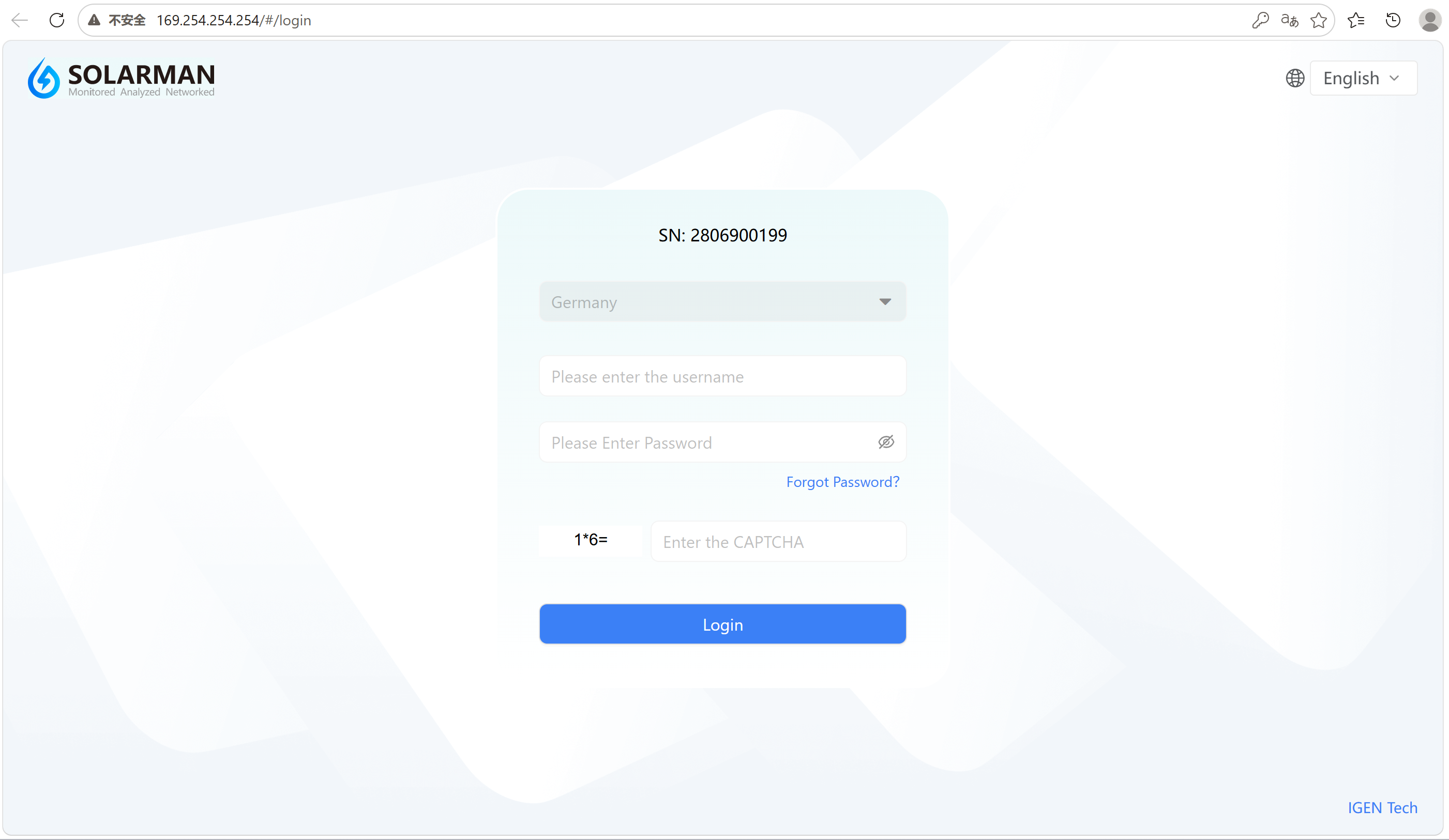
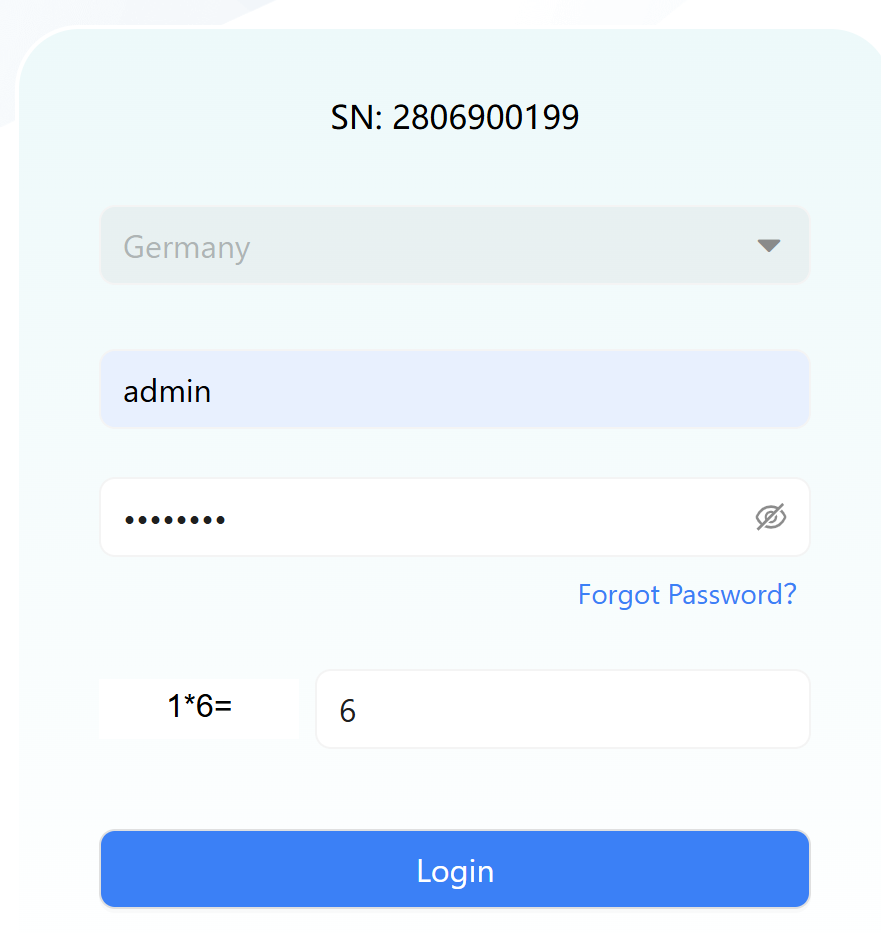
- Enter the following address in the browser: https://169.254.254.254 and press Enter.
- On the login page, select your country/region.
- Enter the username and password, then click Login to enter the system.
This method is used when the device has already been connected to the network via the mobile app.
Steps:
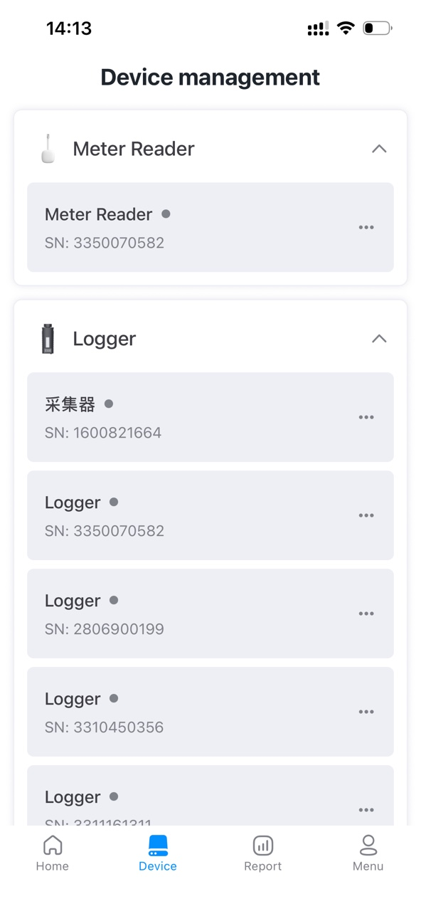
- Complete device addition and network configuration in the mobile app.
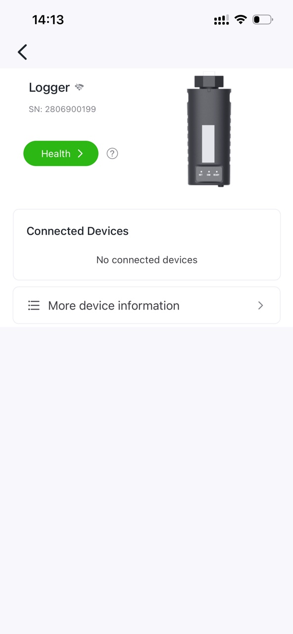
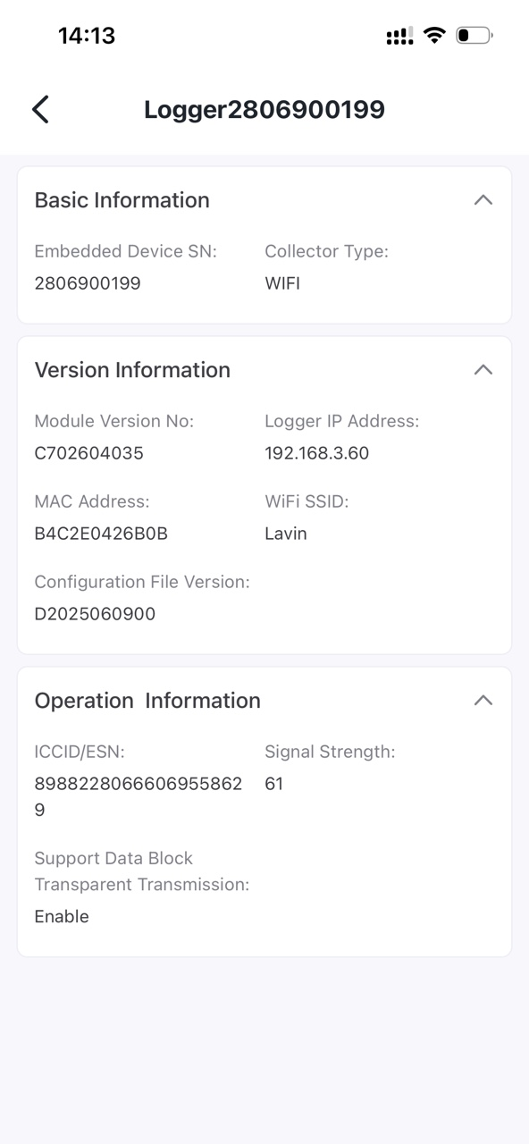
- Go to the device details page in the app to check the current device IP address.
- Ensure the PC and device are on the same local network (same router).
- Enter the device IP address in the browser (e.g., https://192.168.xxx.xxx).
- Enter the username and password, then click Login.
This LAN access method requires the device to be successfully connected to the network. If access fails, please check the network status or use the wired connection method.
Please select the correct country/region carefully. It cannot be changed after the initial selection.

2.3 Change Password on First Login
For security reasons, users must change the initial password upon first login before continuing to use the system.
Description
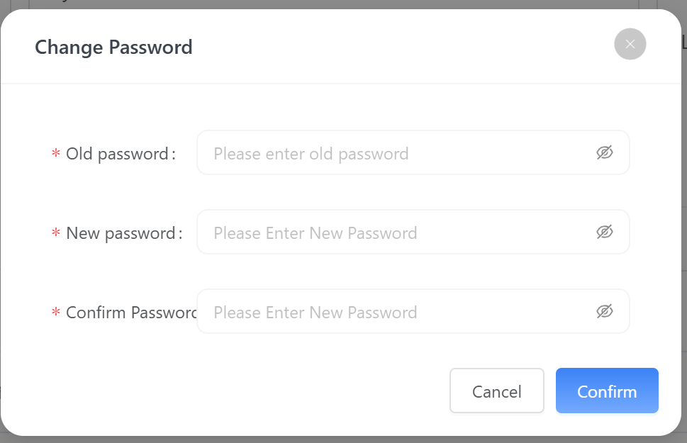
After the first login, the system will automatically display a “Security Risk Warning” prompting the user to change the password. This is a mandatory step, and the system cannot be accessed until the password is updated.
Procedure
Users must enter the following information:
- Old Password: Enter the current initial login password
- New Password: Set a new password
- Confirm Password: Re-enter the new password for confirmation
After completion, click Confirm to update the password.
It is recommended that the password meets the following criteria:
- Includes uppercase letters, lowercase letters, numbers, and special characters
- Minimum length of 8 characters
- Avoid simple or commonly used passwords (e.g., 123456, admin)
- The password is an important credential for device management. Please keep it secure.
- If the password is forgotten, it cannot be recovered through the system. It can only be reset via the device RESET button.
- After performing RESET:
- The password will be restored to the default value;
- Device configurations will need to be reconfigured.
- It is recommended to securely record your password.
- Change the password regularly to improve security.
- Avoid sharing credentials among multiple users.
After successful password change, the system will return to the login page. Re-enter the updated username and password to continue device configuration and management.
2.4 Forgot Password
If users forget their login password, they can refer to the “Forgot Password?” option for reset instructions.
Description
After clicking Forgot Password on the login page, the system will display a reset prompt guiding users to recover the password via the physical device.
Reset Method
To reset the administrator password:
- Locate the RESET button on the device;
- Use a pin tool to press and hold for 5–10 seconds;
- The device will restore factory default settings, including the default password.
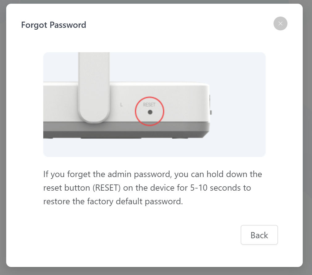
- The RESET button is usually located on the side or bottom of the device (as shown above).
- Keep the device powered on while pressing the button.
- After releasing the button, the device will automatically complete the reset process.
- After factory reset, all custom configurations may be lost.
- It is recommended to reconfigure the password immediately after reset.
- If the issue persists after multiple attempts, check device status or contact technical support.
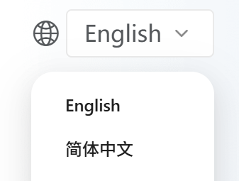
2.5 Language Switching
On the system homepage, hover over the ![]() icon and select the desired language from the dropdown menu.
icon and select the desired language from the dropdown menu.
3. Gateway Settings
In the HEMS Configuration module, navigate to the Gateway settings page to view and manage the device’s network connection status. The system supports multiple communication methods, including LTE, WLAN, WAN, and LAN, to meet different networking scenarios.
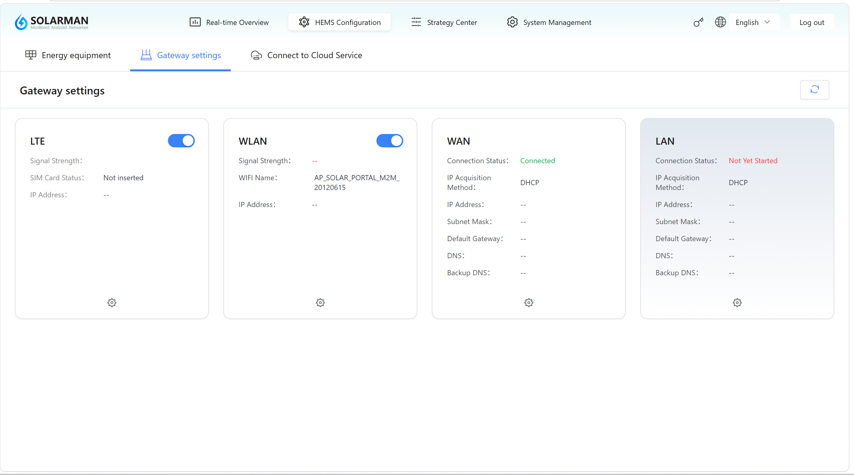
3.1 Overview
This page displays the current network connection status in a card-based layout. Users can view real-time network information and access corresponding configuration options.
The refresh button in the upper-right corner ![]() is used to update the current network status.
is used to update the current network status.
3.2 Network Types
- LTE
- WLAN
- WAN
- LAN
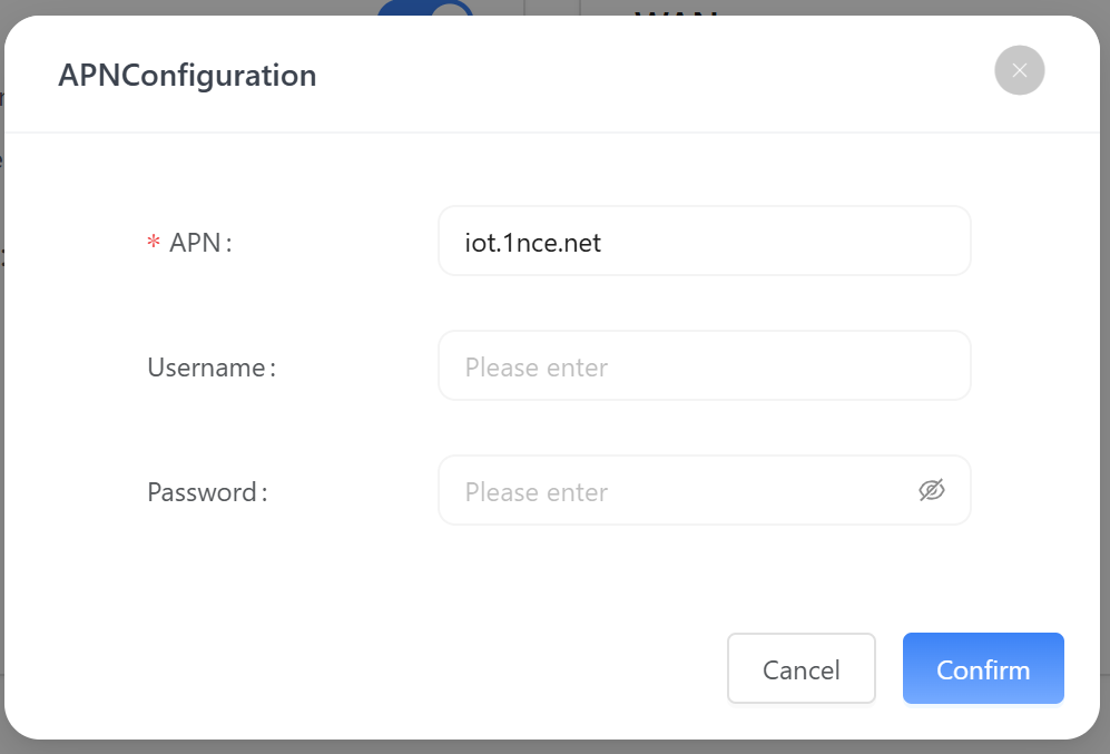
Cellular Network
Used to connect the device via a mobile network. Suitable for scenarios without wired internet access or for remote deployment.
Key information includes:
- Signal Strength: Current cellular signal quality
- SIM Card Status: Whether the SIM card is properly inserted
- IP Address: Assigned network address
Click the settings icon ![]() to configure:
to configure:
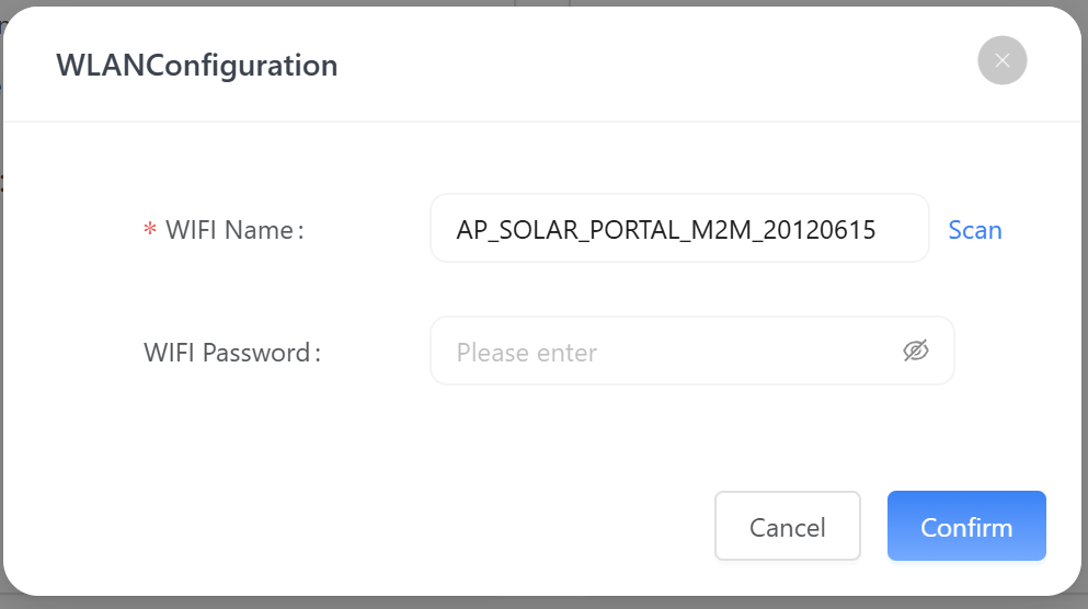
Wireless Network
Used for Wi-Fi-based network connectivity, suitable for environments with wireless coverage.
Key information includes:
- Signal Strength: Wi-Fi signal quality
- WiFi Name: Name of the connected Wi-Fi network
- IP Address: Assigned IP after connection
Click the settings icon ![]() to configure:
to configure:
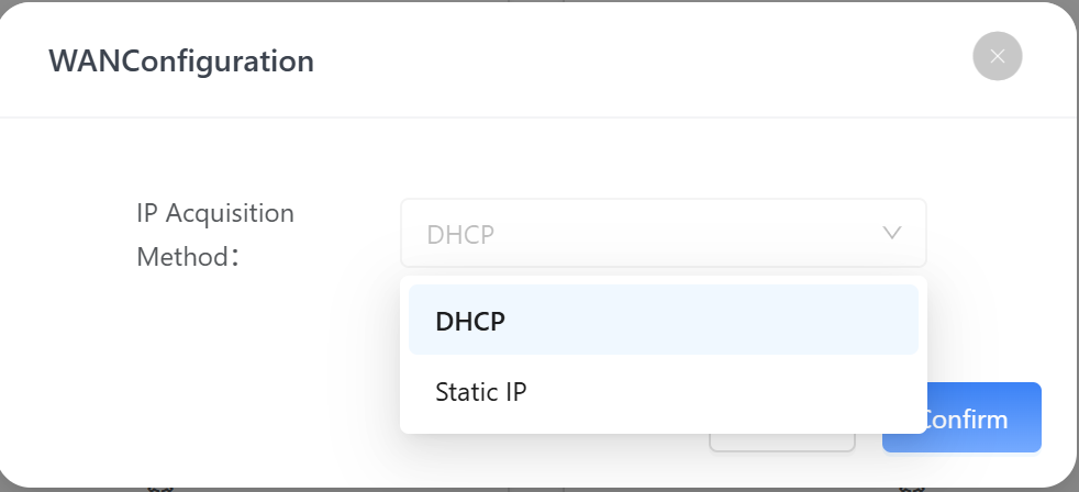
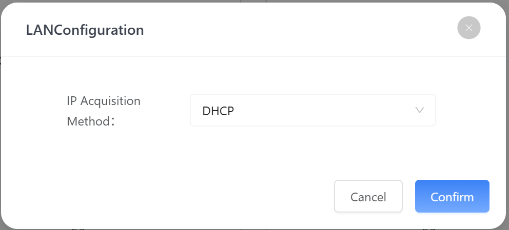
Wide Area Network / Wired Connection
Used for connecting to an external network via Ethernet (e.g., router). This is generally the recommended stable connection method.
Key information includes:
- Connection Status: Whether the network is successfully connected
- IP Acquisition Method: e.g., DHCP (automatic assignment)
- IP Address / Subnet Mask / Gateway
- DNS / Backup DNS
Click the settings icon ![]() to configure:
to configure:
Local Area Network
Used for internal communication or local debugging.
Key information includes:
- Connection Status (e.g., not started)
- IP Acquisition Method
- IP address and other network parameters
Click the settings icon ![]() to configure:
to configure:
3.3 Instructions
- Each network module provides a configuration entry for accessing detailed settings.
- Users can enable or disable network interfaces based on actual requirements.
- It is recommended to enable only one primary network connection to avoid conflicts.
3.4 Status Description
| Connection Status | Color | Description |
|---|---|---|
| Connected | Green | Network is working normally and data communication is available |
| Not Started / Disconnected | Red or Gray | Network is unavailable or not enabled |
- It is recommended to select network types based on the actual environment and avoid enabling multiple primary connections simultaneously
- If a network issue occurs, click the refresh button
 or check the corresponding configuration
 - When using LTE, ensure that the SIM card is properly inserted and has an active data service plan.
Once the network is successfully connected, the device can communicate with the cloud platform or local system for data upload and remote management.
4. Device Access Configuration
Device access in the system is a prerequisite for energy data collection and management. Users can integrate field devices into the platform for centralized management via the “Add Device” function.
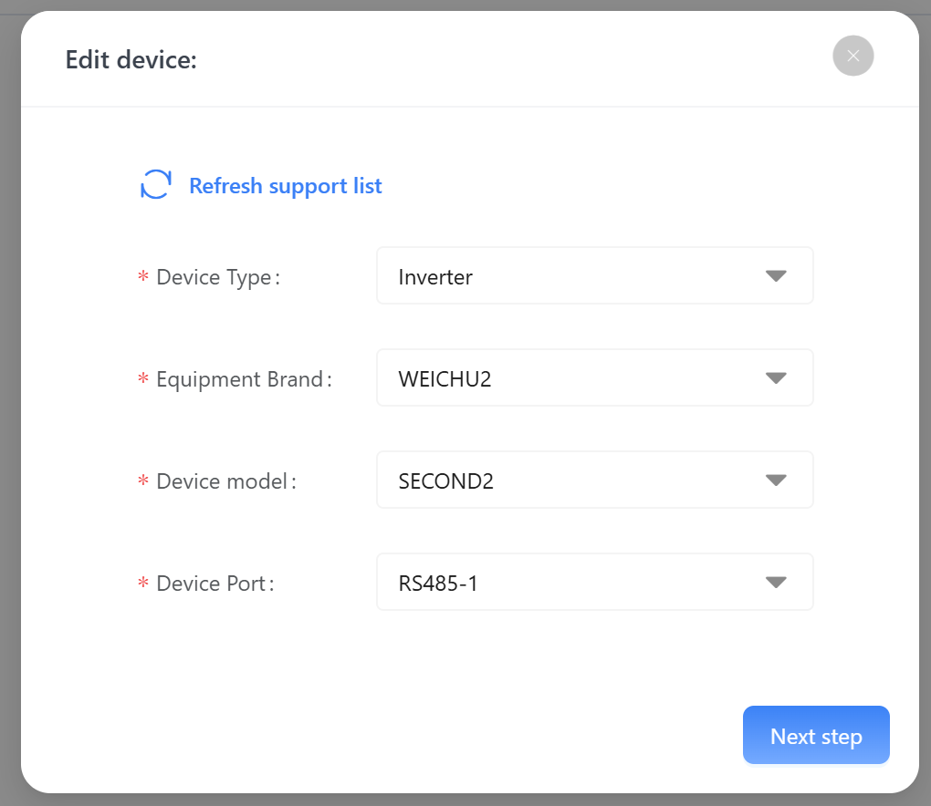
4.1 Add Device (Basic Information Configuration)
After logging into the system, go to the HEMS Configuration module. Under the Energy equipment tab, click the Add Device button in the upper-right corner. The “Add Device” window will appear.
Page Function Description
- Click Refresh support list to update the currently supported device types and models. This ensures the latest device library is available for selection.
- Users must complete the following fields:
| Parameter | Description |
|---|---|
| Device Type | Select the category of the device (e.g., inverter, meter, energy storage system). This determines the available brands and models. |
| Equipment Brand | Select the manufacturer or brand name of the device. |
| Device Model | Select the corresponding model under the chosen brand. |
| Device Port | Refers to the communication interface or channel used by the device (e.g., RS485, P1, LAN, LoRa). It is used to establish data communication between the device and the system. |
- Ensure the selected device model matches the actual device; otherwise, communication may fail.
- If the required model is not found, click “Refresh support list” to update the device library.
- The device port must match the actual wiring method and communication protocol.
- Ensure the device is powered on and ready for communication before adding it.
4.2 Communication Parameter Settings
After completing the basic device information, click Next step to enter the communication parameter configuration page. This page is used to define communication settings between the device and the system and is critical for successful data acquisition.
Parameter Description
This configuration page is dynamically generated based on different device brands and models. The following example shows inverter configuration parameters.
Users must configure the following parameters according to the actual device communication settings:
| Parameter | Description |
|---|---|
| Baud Rate | Communication speed in bps (e.g., 1200, 2400, 4800, 9600). |
| Parity | Data verification method: - NONE (no parity) - EVEN (even parity) - ODD (odd parity) |
| Data Bits | Length of valid data bits per frame, typically 5, 6, 7, or 8 bits. |
| Stop Bits | Indicates the end of a data frame, typically 1 or 2 bits. |
| Communication Address | The device address on the communication bus (e.g., Modbus address). Note: Each device on the same bus must have a unique address. Default is usually 1, depending on device configuration. |
After completing the configuration, click Confirm to add the device. To modify previous settings, click Previous to return.
- Communication parameters must exactly match the device settings; otherwise, the device cannot be recognized.
- On the same RS485 bus, the communication address must be unique.
- If communication fails, check the following first:
- Baud rate consistency
- Correct device address
- Proper wiring (A/B polarity)
If you need to add more devices, repeat the steps above. A maximum of 10 devices can be added.
4.3 Device Access Status and Management
After completing device addition and communication configuration, the system returns to the Energy equipment list page. Successfully added devices are displayed as cards.
Device Status Description
After adding a device, it will appear in the list by default. However, some functions (such as data viewing) are only available after successful communication is established.
Users can click the refresh icon in the upper-right corner ![]() to update device status and available functions.
to update device status and available functions.
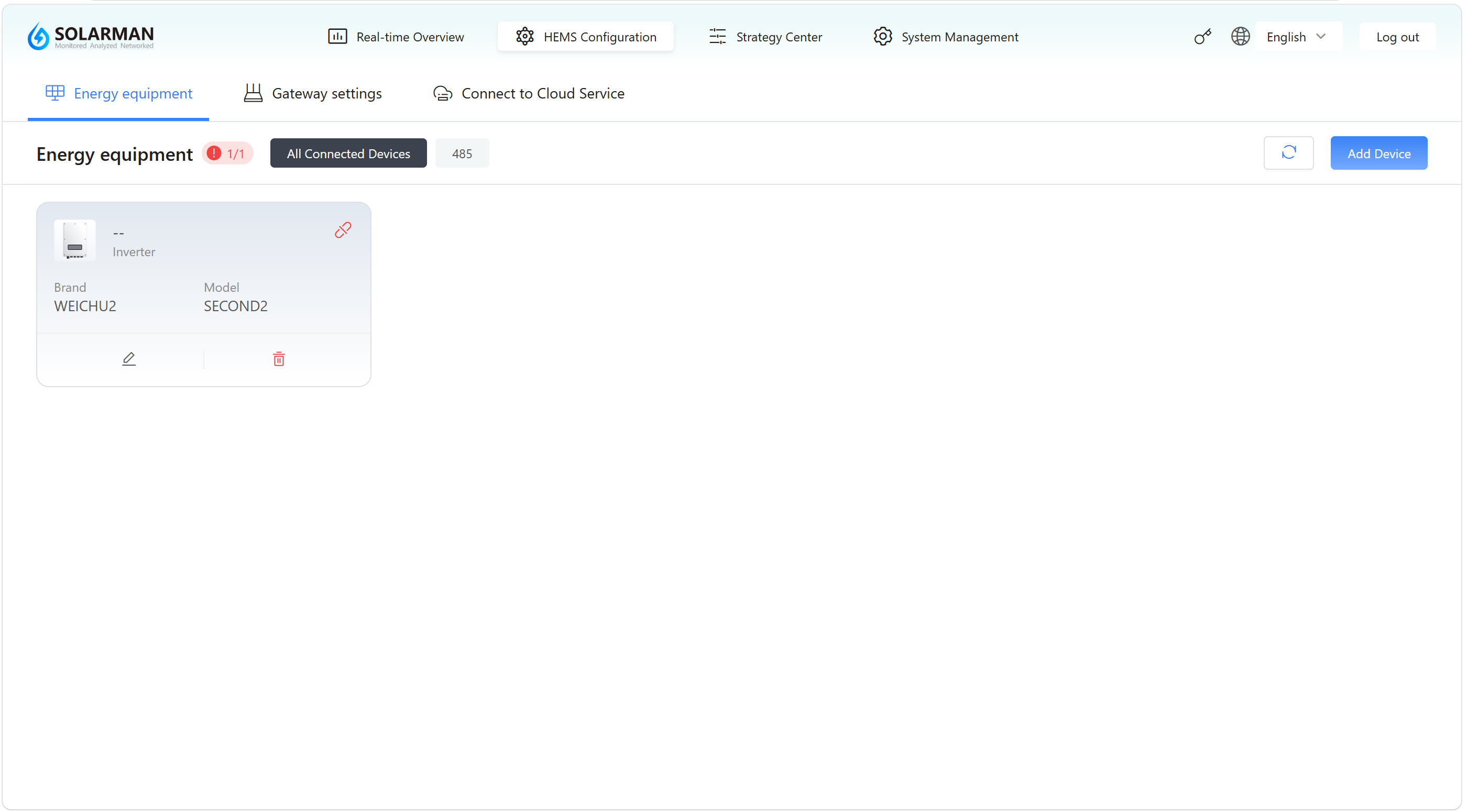
Device Card Information
Each device is displayed as a card containing the following information:
- Device ID / SN
- Device Type
- Brand Information
- Device Model
This allows quick identification of connected devices.
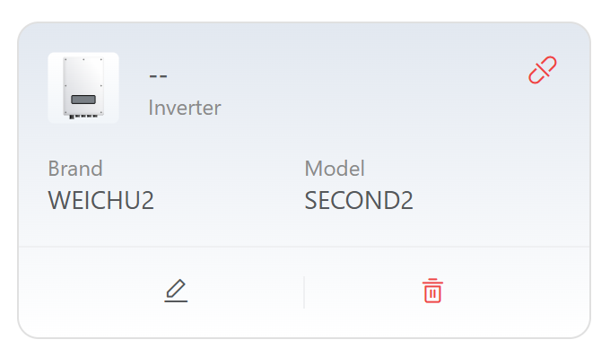
Function Buttons
Each device card provides the following actions:
1️⃣ Edit Device ![]()
Used to modify device basic information or communication parameters.
2️⃣ View Device Data ![]()
Used to access the device data page to view operating data and communication status. Control commands can also be issued for the current device.
The displayed data metrics vary depending on device type and requirements.
Once communication is successfully established, the system will continuously collect and update device data. Users can monitor and analyze the data in real time via the device detail page.
- The
 button becomes available only after clicking Refresh
 - If it is not displayed, it indicates that device communication has not yet been established or the status has not been updated
3️⃣ Delete Device ![]()
Used to remove the current device. After deletion, the device must be added again before it can be used.
5. Cloud Service
In the HEMS Configuration module, navigate to the Connect to Cloud Service page to configure communication between the device and cloud platforms or third-party platforms, enabling data upload and remote management.
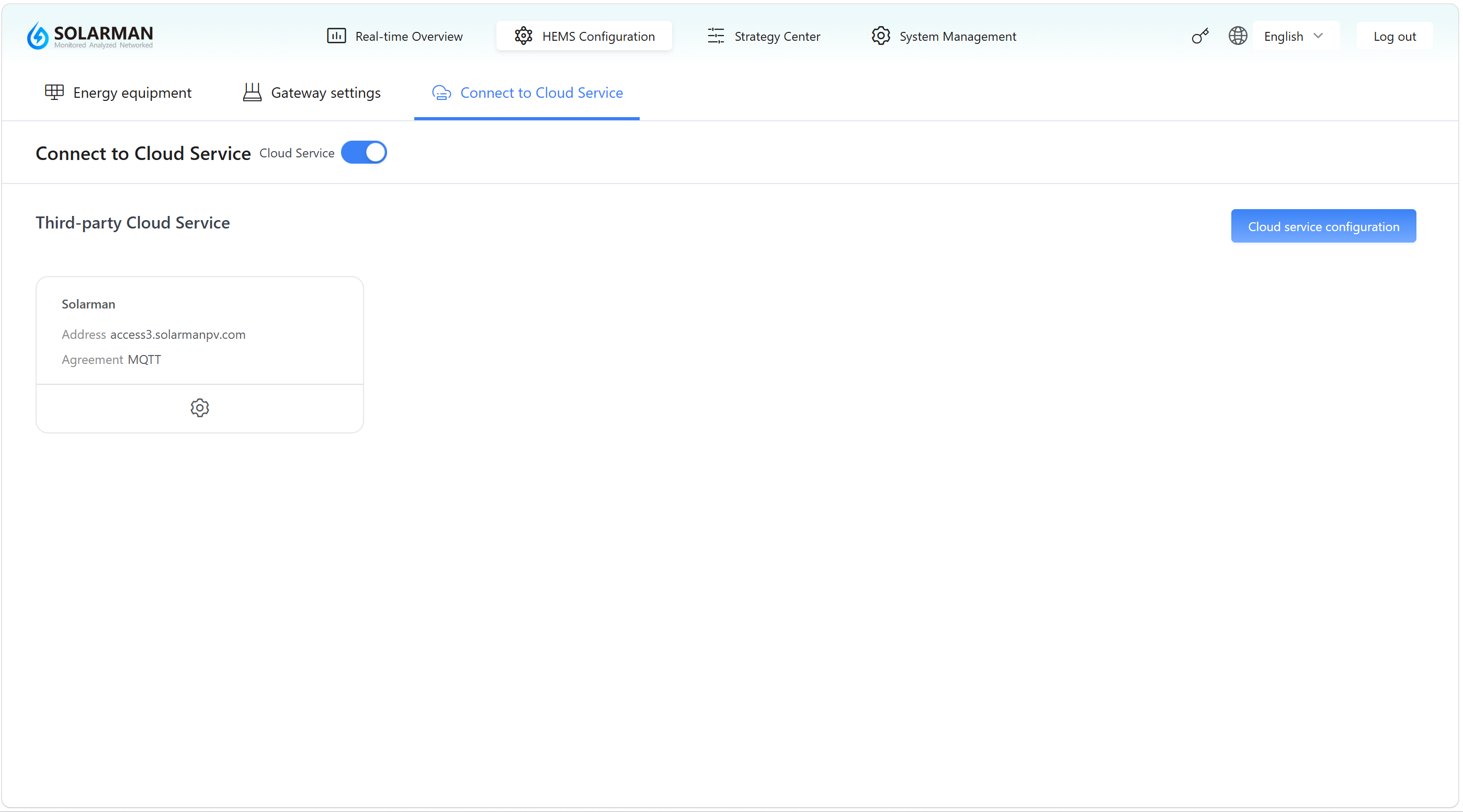
5.1 Overview
This page is used to manage the device’s cloud connectivity status. Cloud services can be enabled or disabled, and corresponding connection parameters can be configured.
When enabled, the device can upload operational data to the cloud for remote monitoring, data analysis, and platform integration.
5.2 Page Description
1️⃣ Cloud Service Switch
The switch at the top of the page controls whether cloud connectivity is enabled.
 Enabled: The device will attempt to connect to the cloud platform
 Disabled: The device runs locally without uploading data
2️⃣ Third-Party Cloud Service List
The list below shows available cloud platforms, such as:
- Platform Name: Solarman
- Server Address: access.solarmanpv.com
- Protocol: MQTT
Each cloud service card includes a settings button ![]() :
:
- Enable: Device sends data to the platform
- Disable: Device stops uploading data
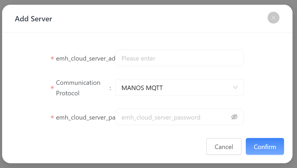
3️⃣ Configuration Entry
The Cloud service configuration button on the right provides access to detailed cloud setup parameters (e.g., account, keys, topic, etc.).
5.3 Instructions
- Turn on the Cloud Service switch
- The system uses Solarman as the default cloud platform
- To configure a third-party cloud platform, click Cloud service configuration
- Fill in required parameters (e.g., server address, authentication information)
- Save and return
5.4 Status Description
| Status | Description |
|---|---|
| Enabled | The device connects to the cloud platform and uploads data |
| Disabled | The device runs locally without cloud communication |
- Ensure the device network is properly connected before enabling cloud services (see Gateway Settings).
- The cloud platform address and protocol must match the actual configuration.
- If connection fails, check:
- Network status
- Cloud platform configuration
- Whether the device has internet access
Once successfully connected to the cloud service, users can view device data via the corresponding cloud platform or mobile app for remote monitoring and management.