Product Overview
1. Model Information
This document mainly covers the following product models: EMH-2-RG and EMH-2-R.
Model Naming Convention
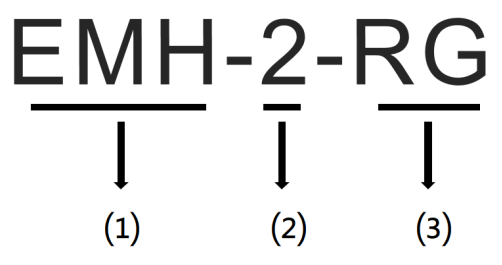
| No. | Description | Value |
|---|---|---|
| ⑴ | Product Identifier | EMH: Home Energy Management Hub |
| ⑵ | Product Generation | 2: Second-generation product |
| ⑶ | Communication Method | R: Supports LoRa communication G: Supports 4G communication |
2. Application Scenarios
The EMH-2 is a smart device specifically designed for residential energy management applications. By monitoring, analyzing, and optimizing household energy consumption in real time, it helps users reduce energy costs, save electricity expenses, and improve the intelligence of home energy usage.
The device supports multiple interfaces and can seamlessly integrate with inverters, batteries, EV chargers, SG Ready heat pumps, P1 smart meters, and other devices. It enables centralized control and optimized management of photovoltaic generation, energy storage, EV charging, and household power consumption.
Typical Applications
- Designed for residential energy management in Europe, helping users optimize energy usage and improve energy cost efficiency in household scenarios.
3. Product Advantages
Core Value
- Cost Reduction: Optimize the use of solar power, battery storage, and grid electricity for the most economical energy consumption.
- Increased Savings: Supports energy planning based on electricity tariffs to enable peak-valley arbitrage.
- Higher Efficiency: Supports local and remote monitoring and management of home energy systems, improving operation and maintenance efficiency.
- Better User Experience: Provides a visualized UI for intuitive display and monitoring of energy data.
Product Features
- Supports integration with various new energy devices such as inverters, batteries, EV chargers, and heat pumps.
- Supports integrated management and scenario linkage of solar generation, energy storage, EV charging, and household loads.
- Supports multiple communication methods including 4G, WiFi, and Ethernet for uploading data to the cloud platform, enabling convenient remote monitoring and management.
- Built-in local management interface for viewing power generation, energy storage, and electricity consumption locally.
- Supports multiple energy management strategies to optimize energy usage, reduce electricity costs, and improve energy efficiency.
- Complies with the EN18031 IoT cybersecurity standard.
4. Product Structure
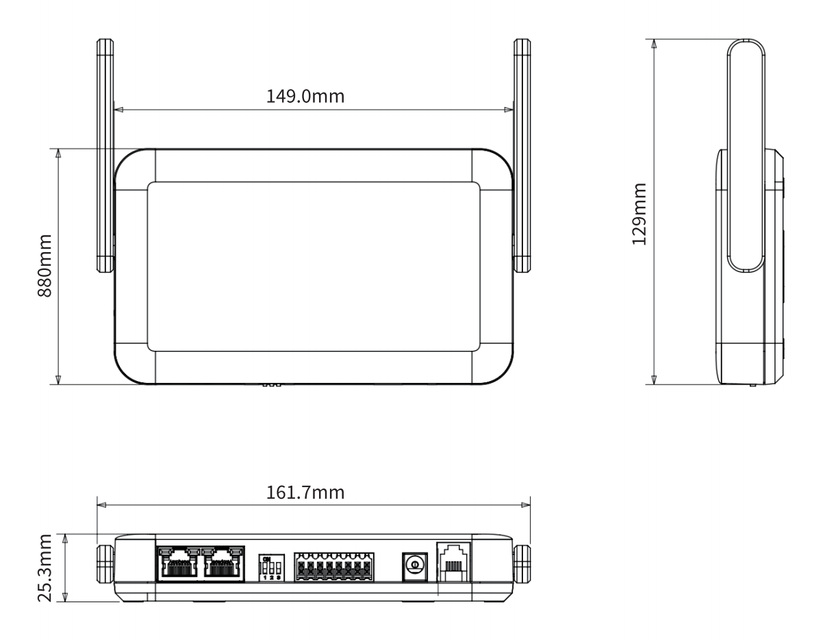
EMH-2 dimensions (unit: mm, dimensional tolerance ±2%)
5. Appearance Overview
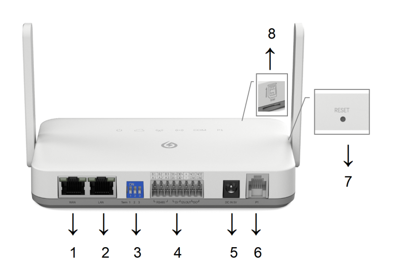
Appearance and Interfaces
| No. | Interface | Description |
|---|---|---|
| 1 | WAN Port | RJ45 Ethernet port (with indicator LEDs). |
| 2 | LAN Port | RJ45 Ethernet port (with indicator LEDs). |
| 3 | 3-Bit DIP Switch | Used to configure the 120Ω termination resistors for the 3 RS485 channels: - ON: Enable 120Ω termination resistor - Default: Disabled |
| 4 | 8Px2 Terminal Connector | Detailed pin definitions are provided in the table below (8Px2 Terminal Pin Definitions). |
| 5 | DC Power Input | External DC power supply input: DC 5V/2A. |
| 6 | RJ12 Female Port (P1) | Used to connect a P1 smart meter. |
| 7 | Reset Button (RESET) | Used to reboot the device or restore factory settings. |
| 8 | Micro SIM Card Slot | Insert the SIM card with the metal contacts facing upward and the notch facing outward. Only available on the 4G version. |
8Px2 Terminal Pin Definitions
| No. | Pin Name | Function | Description |
|---|---|---|---|
| 1 | B1 | RS485 Channel 1 | RS485 Channel 1 Data B |
| 2 | A1 | RS485 Channel 1 Data A | |
| 3 | B2 | RS485 Channel 2 | RS485 Channel 2 Data B |
| 4 | A2 | RS485 Channel 2 Data A | |
| 5 | B3 | RS485 Channel 3 | RS485 Channel 3 Data B |
| 6 | A3 | RS485 Channel 3 Data A | |
| 7 | DI1+ | DI Channel 1 | DI Channel 1 Positive Signal |
| 8 | DI1- | DI Channel 1 Reference Ground | |
| 9 | DI2+ | DI Channel 2 | DI Channel 2 Positive Signal |
| 10 | DI2- | DI Channel 2 Reference Ground | |
| 11 | + | 12V Isolated Power Output | DC 12V@100mA isolated power output |
| 12 | - | Isolated power reference ground | |
| 13 | NO1 | DO Channel 1 | DO Channel 1 Normally Open Terminal |
| 14 | COM1 | DO Channel 1 Common Terminal | |
| 15 | NO2 | DO Channel 2 | DO Channel 2 Normally Open Terminal |
| 16 | COM2 | DO Channel 2 Common Terminal |
LED Indicator Description
| Indicator | Operating Status | |||
|---|---|---|---|---|
| Icon | Description | On | Blinking | Off |
| Power / System Status Indicator | 1. After power-on, all 6 LEDs light up for 30 seconds and then turn off, indicating successful startup. 2. Remaining solid on indicates system program error. | System operating normally | Power-on failure / system error | |
| Server Connection Indicator | Connected to server successfully | Connecting to server | Server connection failed | |
| Router / Base Station Connection Indicator | Connected successfully | Connecting | 4G disabled / connection failed | |
| LoRa Indicator | Indicates connection status between the collector and LoRa sub-devices / also compatible with Bluetooth connection indication; solid on means connected normally | LoRa/Bluetooth communication active | Connection failed | |
 | Serial Port Indicator | RS485 device connected normally | N/A | Connection failed |
| P1 Indicator | Connected normally | N/A | Connection failed | |
Firmware Upgrade: During firmware upgrade, the COM and P1 indicators blink simultaneously. The system will automatically reboot after the upgrade is completed.
Button Description
| Button | Reset | Short press the RESET button (duration < 10s): release the button after all indicators light up, and the device will reboot. |
|---|---|---|
| Reload | Press and hold the RESET button (duration ≥ 10s): keep holding until all indicators turn off, then release to restore factory settings. |
6. Accessories
Power Adapter
Supplied with a European-standard AC power adapter as the mains input power source. It uses a DC 2.5 connector (cable length: 1m) to power the EMH-2.

| Input Characteristics | Minimum | Rated Value | Maximum |
|---|---|---|---|
| Input Voltage | 90Vac | 100Vac~240Vac | 264Vac |
| Input Frequency | 47Hz | 50Hz/60Hz | 63Hz |
| Rated Load | Output Voltage | |
|---|---|---|
| Minimum | Maximum | |
| 0.1A | 2A | +5V±5% |
P1 Meter Cable
Supplied with a standard 1.5m RJ12 connection cable.